OUR PRODUCTS
CHEZY PP INSPECTION CHAMBER
-
 THE ADVANTAGES
The Advantages Of CHEZY PP Inspection Chamber Over The Traditional Brick Chamber
- High compressive strength and is fully functional even with 2 inches (50 mm) of ground settlement or flooding.
- 100% water and air tight connections, completely leak proof.
- Long life,will last for hundreds of years, chemical resistant, no effect on Chamber by H2S or sewage.
- Very smooth inner walls, no cockroaches or vermin.
- Very little labour required (80% less) - Very ECONOMICAL.
- Aesthetically pleasing. Very strong with UV stabilized locked down cover. -
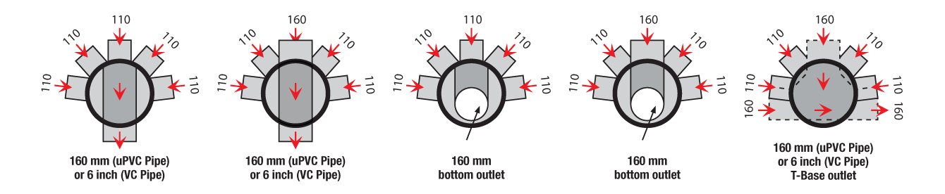
FLEXIBLE CONFIGURATIONS
2 pieces of 110 plugs are provided with every chamber for unused inlet connections.
-
LOOSE PARTS
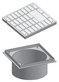
Cover & Collar
The Chezy PP Inspection Chamber cover and collar is made out of high impact and UV stabilized ABS. It has been tested to BS EN 1253-4 for watertightness, odour tightness and backflow tightness. It has been awarded a Class BT.
The Chezy chamber complies to application area code U (outside the building structure) and application area code D (within the building structure), hence the classification UD for our chambers.
The collar fits into the outside of the riser and is sealed by a water tight rubber seal. The matt finished cover (for anti slip) is screwed down in the collar for security and reduced risk of unwated removal. The UV stabilized Chezy cover and collar have been tested for their load streight. (Medium Duty – 300 KG, Heavy Duty- 1500 KG.)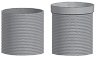
Riser
The chamber riser prices are designed for dry jointing and have strengthening ribs for additional structural strength and for bonding with the back-fill.
The riser pieces can be simply built up to the required height between the chamber base and cover by secure push fit sealing rings for water tight joints. The Chezy riser pieces have strengths in access of 0.7 KN/m2.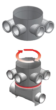
Body
The section of the PP Inspection Chamber is joined to the base by a simple dry jointing method (rubber ring), providing an instant water tight joint. It has 110mm inlets 45 degrees to the central channel) and the whole body can be rotated about the base, so that the directions of the inlets can be shifted to the direction where most of the incoming pipes are coming into the chamber. This results in savings in the number of fitting used. Push fit jointing using rubber rings is done between the uPVC pipes and the PP Inspection Chamber.
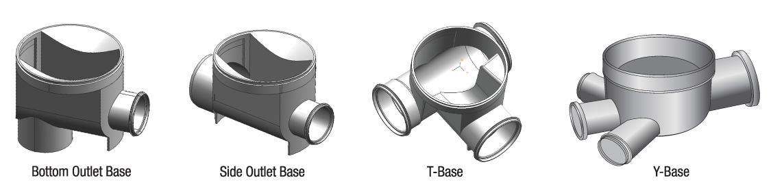
Base
The chamber base is available for both 110mm and 160mm drainage layouts, with branch inlets desgined to optimize flow directions. Chezy PP Inspection Chambers come with either side or bottom outlets and can be joined to uPVC or vitrified clay (VC) pipes (160mm). The 150mm central channel in the chamber base is designed with a built-in fall for good flow performance.
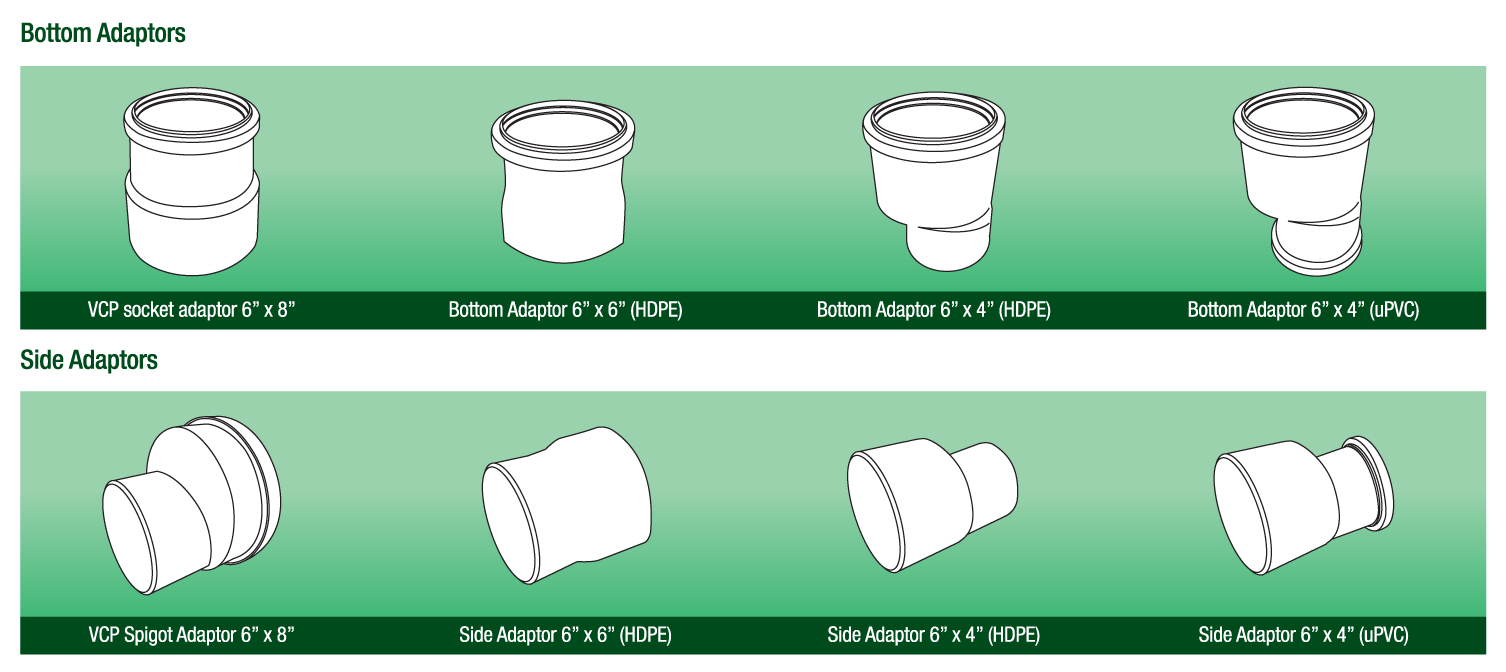
Adaptors
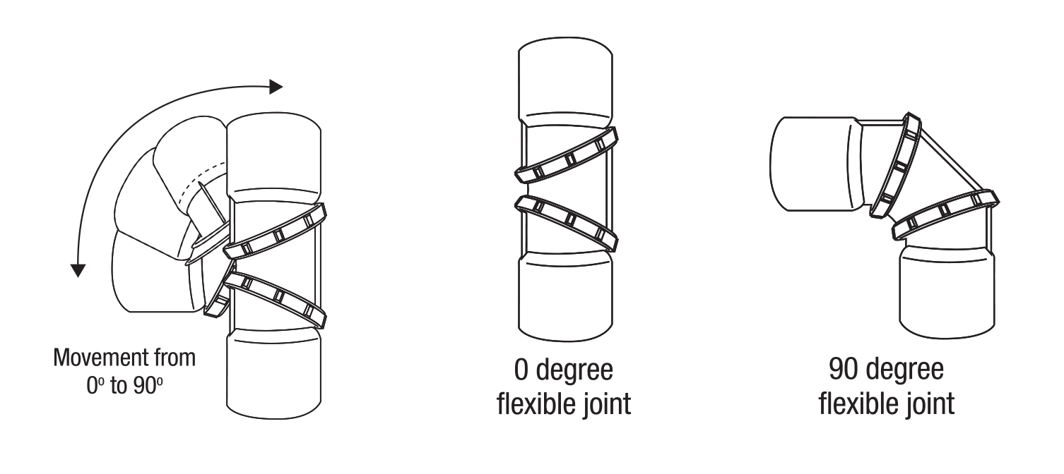
Flexible Bend
The flexible bend is meant for connections to the sockets on the inspection chamber in cases where the incoming pipes are not in alignment with the sockets in the inspection chamber.
-
THE DO's AND DON'Ts
The DO's
1. Remember that 4 of the inlets are 250mm (10 inches) above the outlet of the chamber. Calculate accordingly for the proper invert level for connection to other inspection chambers or the main line.
2. Use a liquid level gauge to ensure that the level is flat on the top of the chamber before backfilling.
3. Lubricate rubber rings using silicone, soap water or other suitable lubricants when joining to incoming our outgoing pipes.
4. Place the Chezy inspection chamber first, than run the pipes into the building. This will ensure connections with as little bends as possible are used (recommended)/ other methods can be used, depending on construction stage and site requirements.
5. Follow bedding and installation methods.
6. Use 45 degree bends and not 90 degree bends if required to do so. The use of our flexible bend is recommended.
7. Do ensure sufficient protection is made on the inspection chamber during the contruction process. Ensure protection and safety indicators, etc are placed to prevent lorries, excavators, etc from crossing over or near the inspection chamber during the construction process.The DON'Ts
1. Do not force pipe into connections of inspection chamber. If there is resistance into joining with the chamber, it means that there is not enough lubricant on the rubber rings or insufficient chamfer on the pipe.
2. Do not backfill with granular material having particle size larger than 10mm.
3. Ensure that stones, pieces of wood, brick, etc do not press against the chamber body after backfilling. -
DESIGN & REQUIREMENTS
Preformed Plastic Inspection Chambers have been widely used in Europe and the United States for the past 35 years. The Chezy PP inspection chambers have excellent structural integrity, good design and operational performance, water tightness and exceptional resistance the chemicals.
Design and requirements.
The capacity of a sewer system will be determined by the diameter and the gradient of the piping system. Foul drains are normally designed to carry peak discharges at less than full flow (usually to a maximum of 75%) to allow for ventilation of the system. Recommended gradients for water are shown below (minimum flow velocities of 0.76 m/s should be used to avoid the possibility of solid-waste being deposited)

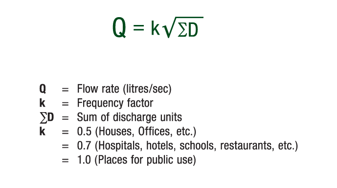
Calculation of flowrate using discharge units
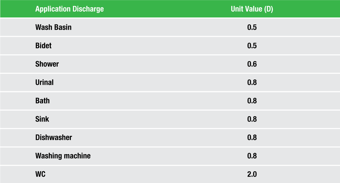
For general calculation purposes (BS EN 12056: Part 2) the above dischange unit values can be used. Flow rates (l/s) in the pipe can be calculated as follows:
Load factors on Chambers vary according to type of soil, compaction during installation and groundwater. An important function of the chamber is to resist these factors and to maintain the hole in the ground. The Chezy PP inspection chamber is light weight and more economical than the traditional chamber, their functional performance is excellent.
-
HOW TO SPECIFY
The sub contractor shall construct the inspection chamber as shown on the accompanying drawings. Every inspection chamber shall have a 150mm central channel and an outlet of minimum internal bore of diameter 150mm. The inspection chamber should be of ample size to accommodate all sewers and to sizes specified in the plans. Inspection chamber body shall be made of polypropylene and the cover and frame of UV stabilized ABS. The inspection chamber use shall be certified to EN 13598–1:2003 and the cover and frame to EN 1253–4:2003. The inspection chamber used shall have a UD rating and the frame and cover a BT rating. All joints with incoming and outgoing pipes shall be of rubber ring type. Joints between the sections of the body shall also be made by rubber ring jointing. UV stabilized locked down ABS frame and cover shall be set on each inspection chamber, level with the ground. The frame shall be properly bedded and fixed. An airtight gasket shall be provided where ever necessary. The frame shall have a minimum concrete surround of 75mm x 75mm flush with the ground level in turf areas and a 150mm x 150mm concrete surround if subject to vehicular traffic. The minimum internal dimentions shall be as followed:

EXCAVATION & BACKFILLING
The subcontractor shall be responsible for the construction of necessary trenches for the piping works including excavation, backfilling work, turfing, making good and general decoration.
When pipe tranches are open, all pipes shall be laid and the trenches shall be backfilled within 24 hours. At all times, safety precautions, warning notices, etc, shall be taken and arrangement made to prevent damage to the pipes.
Turf and topsoil shall be removed carefully and preserve for reinstatement in their original positions. Broken drains and damage to other services shall be reported and indicated. The excavation shall be kept free of water and properly shored up. Other services uncovered shall be adequately supported by slings or other means of protection.
Before the pipes are laid, the bottom of the trench shall be evenly graded, cleared of loose stone and then filled with 4 inches (100mm) layer of sand and backfill with sand around and over the pie to a minimum depth of 4 inches and tamp. The next layer of the backfill shall be at a minimum of 1ft and shall be of material free of stones and rocks, etc. The remainder of the trench shall be filled with available material in an approved manner. The top soil and turfing are then re-instated and the ground made good and generally decorated to the same situation before excavation to the requirements of the Consulting Engineer.
No pipe trenches shall be backfilled unless the buried pipe systems have been inspected and tested to the requirements of the relevant authorities and to the specifications.TESTING
The consulting engineer reserves the right to request for water and air or smoke test for hydraulic performance tests. These tests are to be carried out by the sub contractor at his expense including the furnishing of the necessary equipment.
1. WATER TEST
The water test of drains shall be carried out as follows: i) All openings below the top section shall be hermetically sealed, and, if considered necessary by the consulting engineer, tested the when additional static head of 15 feet. ii) The shall be filled with water to the highest point. iii) The water level shall be maintained by the system at its filled height for a period of fifteen (15) minutes. iv) The quantity of water added to maintain the water level must not exceed three (3) measured gallons for every fifty (50) joints, proportionately more or less for a lesser or greater number of joints. v) Every pipe and joints shall be carefully examined for leaks while the system is filled with water.
2. SMOKE TEST
The smoke has to be carried out in the following manner: i) Smoke from a “smoke generator” shall be forced into the system under pressure not less than the equivalent of 1” water gauge. ii) Each opening where smoke appears shall be sealed until all openings are closed. iii) The pressure on the smoke shall be maintained for five (5) minutes after the last closure is made.
3. AIR TEST
Air test may be performed by inserting expanding rubber testing plugs in the lower and upper ends of the main soil pipe and main ventilating pipes and sealing the plug with water necessary.
The testing plug at the upper end of the ventilating pipe should be fitted with the Tee-piece with a cock on each branch. A flexible tube manometer should be fixed to one branch, while air pressure is being introduced into the system through the other branch until the pressure is indicated on the manometer scale.
The applied pressure should be equal to 1 ½” water gauge and should remain at the pressure for a minimum of three (3) minutes to prove the soundness of installation. -
INSTALLATION METHOD